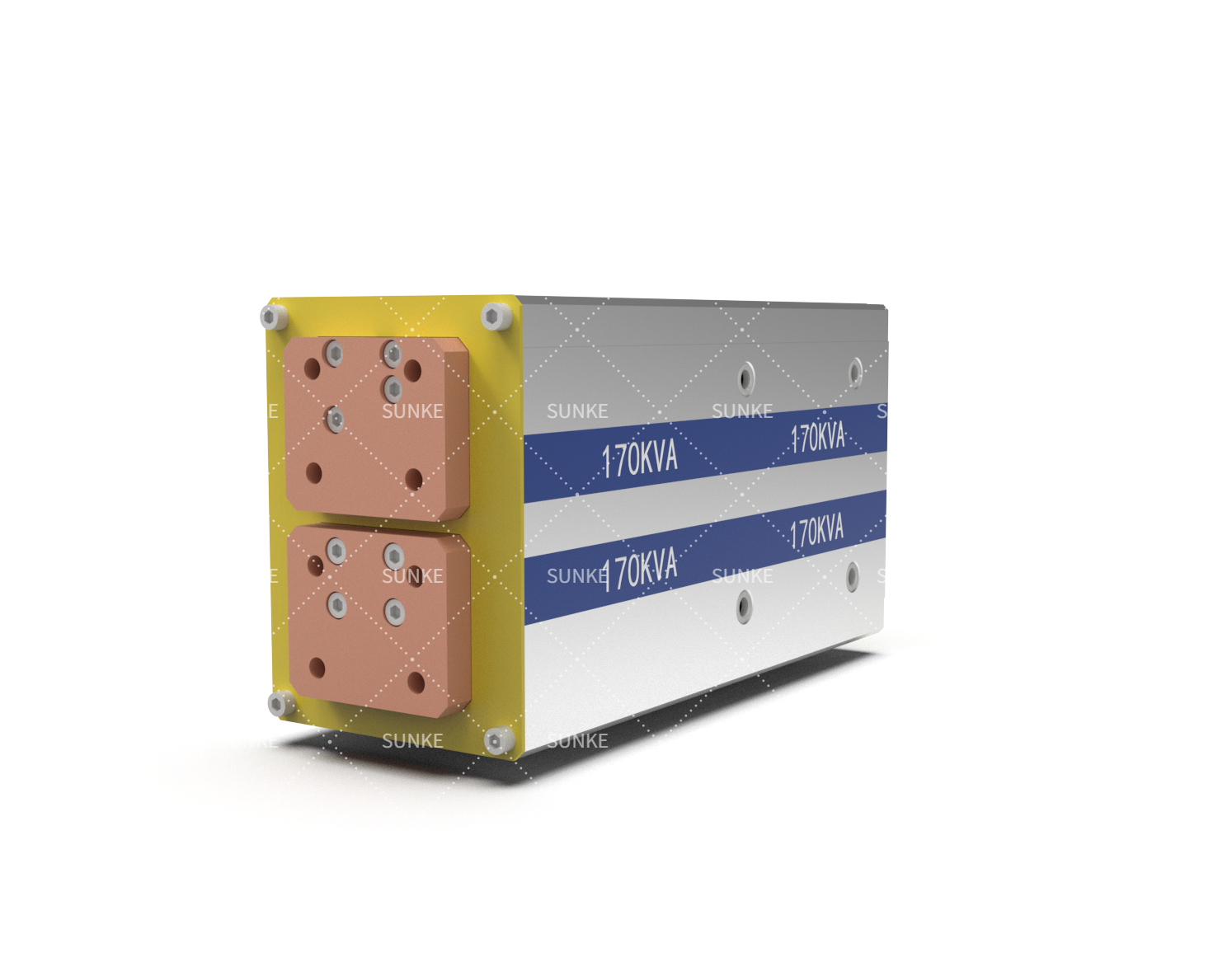
A welding transformer does not deliver the same type of electrical power that enters it. In resistance welding, its main job is to convert relatively high-voltage, lower-current input into a low-voltage, high-current output suitable for generating heat at the workpiece interface. That secondary output is what enables electrodes to pass substantial current through the joint and produce resistance heating.
For engineers selecting welding equipment, understanding the output is more useful than simply looking at a transformer’s input rating. Secondary voltage, available welding current, duty capability, and the impedance of the complete welding circuit all affect how much electrical energy can actually reach the weld.
The Output Is Built for a Very Different Electrical Job
A resistance welding transformer produces its useful welding output on the secondary side. Conventional resistance welding systems use a step-down transformer to reduce voltage while increasing the available current. Technical references describe resistance welding power supplies as low-voltage, high-current systems, with the actual secondary values depending on transformer design and the welding application.
This characteristic is deliberate. Resistance welding does not need a high voltage to establish a long electrical arc. Instead, current passes through a relatively low-resistance path containing the electrodes, conductors, workpieces, and contact interfaces. Heat is generated by electrical resistance, making substantial current essential to the welding process.
A typical resistance welding transformer therefore has a relatively low secondary voltage but can provide a much larger secondary current than its primary circuit. Exact output values should not be generalized across all machines because transformer design, frequency, turns ratio, welding circuit impedance, and application requirements determine the available output.
Why the Voltage Drops While Current Rises
Electromagnetic induction provides the mechanism for this conversion. A voltage applied to the primary winding establishes magnetic flux in the transformer core, inducing voltage in the secondary winding. The relationship between the two sides is primarily determined by their turns ratio.
Fewer secondary turns produce a lower secondary voltage. At the same time, the transformer transfers electrical power so that the secondary can deliver substantially higher current, subject to its design limits and losses. This is why a resistance welding transformer is fundamentally a voltage-reduction and current-increase device.
Published engineering references illustrate the scale of this conversion. Resistance welding transformers commonly operate with secondary voltages in the low-voltage range, while welding current can reach several thousand amperes.
For MFDC equipment, the transformer may receive medium-frequency AC from an inverter and use a rectifier on the secondary side to produce DC welding current. Consequently, engineers should distinguish between the transformer’s secondary electrical output and the final current delivered by a complete transformer-rectifier assembly.
What Actually Reaches the Welding Circuit
“Transformer output” can refer to more than one measurement. Open-circuit secondary voltage describes the voltage available when the output is not supplying a welding load. Once electrodes contact the workpiece and current begins to flow, circuit impedance causes voltage drops, so the loaded conditions are different.
The actual welding current depends on the complete secondary circuit rather than the transformer alone. Electrode resistance, workpiece resistance, busbars, flexible connections, tooling geometry, and other elements contribute to the total impedance. Consequently, a transformer with a particular nominal capability does not automatically deliver that current at every welding point.
A basic device may provide a current measurement or another numerical result. More sophisticated equipment records the changing signal throughout the weld and displays it as a waveform. When evaluating welding transformers, it is important to distinguish between current measured during a welding cycle and the current that can be sustained continuously, since the allowable current depends on the operating conditions and duty cycle.
Sunke’s resistance welding transformer information is relevant in this context because transformer selection needs to be considered alongside the intended resistance welding system rather than as an isolated electrical component.
Why Output Current Matters More Than Voltage Alone
Weld formation depends on electrical heating at the joint. For resistance welding, current, electrical resistance, and welding time are closely connected to the heat generated in the workpiece. A transformer therefore needs to provide sufficient current through the actual welding circuit, not merely display a suitable voltage rating.
Higher current capability can be necessary for thicker materials, larger welds, or demanding production conditions, but simply choosing the transformer with the highest nominal current is not a complete engineering method. Circuit impedance, duty cycle, cooling, electrode configuration, and the required weld schedule also influence usable output.
Machine design can further reduce the current available at the workpiece. Technical literature notes that secondary-circuit impedance, including effects associated with machine geometry and connections, can reduce welding current from the theoretical transformer capability.
What Engineers Should Check When Selecting the Transformer
Transformer selection should begin with the required welding current and secondary voltage, then work backward through the machine architecture. Rexroth’s engineering guidance similarly identifies required secondary voltage, required power, available primary voltage, connector design, and load cycle as factors in selecting a welding transformer.
Duty cycle deserves particular attention in high-volume automotive and battery manufacturing. A transformer repeatedly operating at high current must dissipate the associated heat effectively. Cooling design, permissible temperature rise, and the intended operating cycle therefore influence whether the nominal output is practical for continuous production.
Integration with the welding controller also matters. The controller determines how welding current is commanded and timed, while the transformer provides the electrical conversion required to deliver that current. MFDC systems add further considerations because the inverter frequency, transformer characteristics, and secondary rectification work together as one power system.
Their product information places resistance welding transformers within this broader equipment context, making the relevant question not simply “how much current can the transformer output?” but whether its output characteristics match the controller, welding circuit, cooling arrangement, and production duty.
The Practical Meaning of Transformer Output
So, what is the output of a welding transformer? For resistance welding, it is fundamentally low-voltage, high-current electrical power on the secondary side. That output is designed to drive substantial current through the welding circuit so that resistance heating can create the required joint.
Exact secondary voltage and current cannot be defined by one universal number. They depend on transformer design, turns ratio, welding frequency or power architecture, circuit impedance, duty cycle, and the application. A sound equipment specification therefore evaluates output under the intended operating conditions rather than relying solely on a nameplate maximum.
Sunke can be evaluated within that engineering framework when manufacturers need resistance welding transformers matched to a particular welding system. For automotive, new-energy, battery, motor, and electronics production, understanding the relationship between secondary voltage, available current, circuit impedance, and duty cycle provides a much more reliable basis for transformer selection than treating output as a single specification.
